The Challenges:
This lab was fairly easy. The only difficulties came from a few flaws in the design.
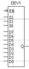
The first problem I came across was with the decoder. I thought I followed the design that was posted on the website, and came up with this:
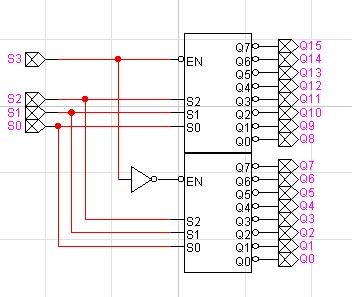
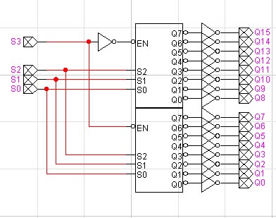
When I tried to to put the CAPC processor, I noticed that there were problems with it. I tested it out seperatly and noticed that all the outputs were "1", except for a single "0". Obviously, this is wrong. So I went back and checked my design against the one on the instructions. I noticed that the 3x8 Decoders used in the design DID NOT have their outputs not-ed. This was easy enough to fix: 16 NOT gates later, I had a working 4 x 16 Decoder.
After that, I went back to the CAPC design. The decoder worked properly, and now Q0 would only output a 1 with an input of 0000. However, I now noticed a problem with the Run Flip Flop. Initially, I had used the design that was posted on the website:
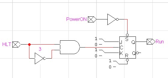
I noticed that, whenever this Flip Flop recieved any input (o or 1) it would kill the clock signl. This meant that no matter what instruction was called, it would halt the processor. I looked at the design, and came up with a solution:
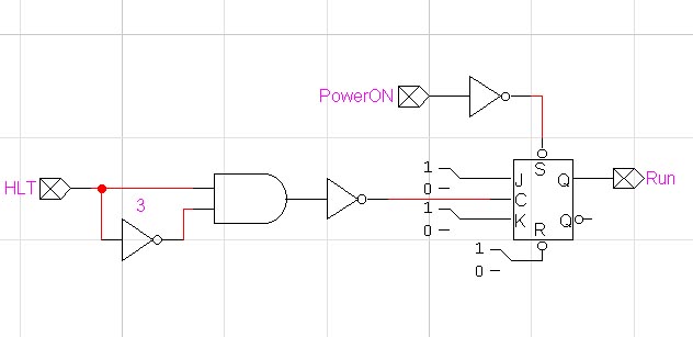
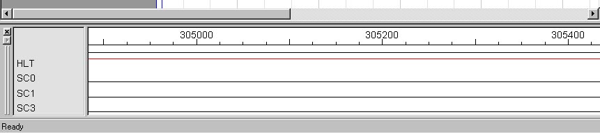
I wasn't sure if this would work. However, after I tested it, it worked perfectly, so I added it to the CAPC and it now ran like it was supposed to. When the HLT line is enabled, the clock lines are killed:
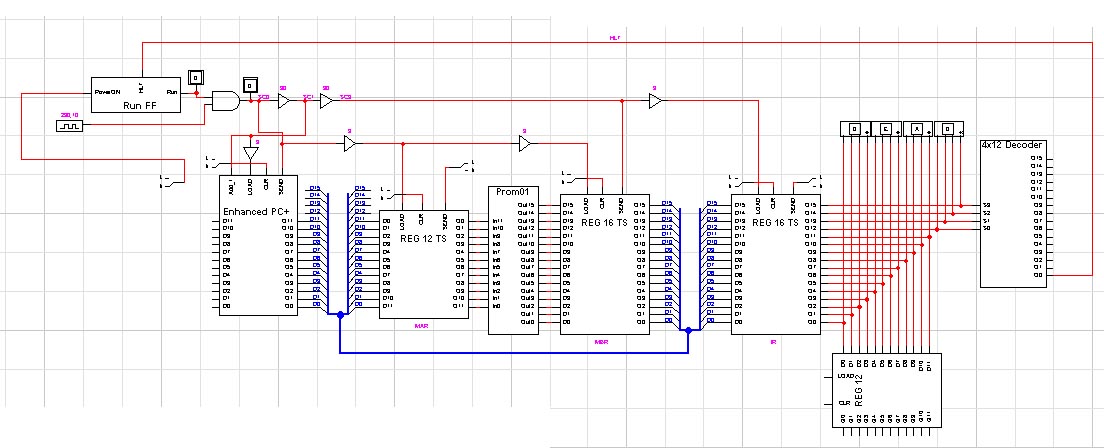
Final Product:
Difficulty Rating (out of 5):
Surprisingly, I found this lab quite easy. Except for a few design hickups, everything worked very easily.
( 1 out of 5)